
Blame
| 62c67d | João Lopes | 2025-03-13 12:01:58 | 1 |  |
| 374ad8 | João Lopes | 2025-03-13 11:57:41 | 2 | |
| 3 | > Departamento de Engenharia Química |
|||
| 4 | > |
|||
| 5 | > Mestrado Integrado em Engenharia Química |
|||
| 6 | > |
|||
| 7 | > Integração e intensificação de processos |
|||
| 8 | > |
|||
| 9 | > Shell and Tubes Heat Exchangers |
|||
| 10 | > |
|||
| 11 | > **Docente** **Responsável:** |
|||
| 12 | > |
|||
| 13 | > Nuno Manuel Clemente de Oliveira |
|||
| 14 | > |
|||
| 15 | > **Integrantes** **do** **grupo:** |
|||
| 16 | ||||
| 17 | João Victor Vieira |
|||
| 18 | ||||
| 19 | > Matteo Gecchele |
|||
| 20 | ||||
| 21 | ||||
| 22 | > **Introduction** **&** **Structure** |
|||
| 23 | > |
|||
| 24 | > The most common type of heat exchanger is the shell-and-tube, usually |
|||
| 25 | > used in a lot of industrial applications. This type of heat exchanger |
|||
| 26 | > has large number of tubes, sometimes several hundred, packed in a |
|||
| 27 | > shell with their axes parallel to that of the shell. The heat transfer |
|||
| 28 | > takes place between two fluid, one flowing inside the tubes and one |
|||
| 29 | > flowing outside the tubes through the shell. Baffles are commonly |
|||
| 30 | > placed in the shell to force the shell-side fluid to flow across the |
|||
| 31 | > shell to enhance heat transfer, to maintain uniform spacing between |
|||
| 32 | > the tubes and, also in order to maintain the turbulent flow inside the |
|||
| 33 | > exchanger. The baffle spacing is usually not greater than a distance |
|||
| 34 | > equal to the inside diameter or closer than a distance equal to |
|||
| 35 | > one-fifth the inside diameter of the shell. |
|||
| 36 | > |
|||
| 37 | > Usually the shell-and-tube heat exchangers have large size and weight, |
|||
| 38 | > and for this reason they are not using in automotive and aircraft |
|||
| 39 | > applications. At both ends of the shell, the tubes open to some large |
|||
| 40 | > flow areas, called headers, where the tube-side fluid accumulates |
|||
| 41 | > before entering the tubes and after leaving them. |
|||
| 62c67d | João Lopes | 2025-03-13 12:01:58 | 42 | >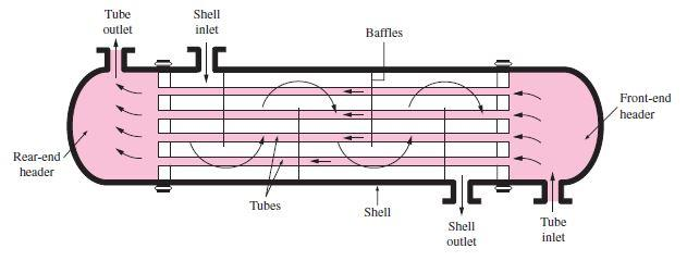 |
| 5b9f6d | João Lopes | 2025-03-13 12:02:35 | 43 | > |
| 374ad8 | João Lopes | 2025-03-13 11:57:41 | 44 | > Shell-and-tube heat exchangers are further classified according to the |
| 45 | > number of shell and tube passes involved. Heat exchangers in which all |
|||
| 46 | > the tubes make one U-turn in the shell, for example, are called |
|||
| 47 | > one-shell-pass and two-tube-passes heat exchangers. Likewise, a heat |
|||
| 48 | > exchanger that involves two passes in the shell and four passes in the |
|||
| 49 | > tubes is called a two-shell- passes and four-tube-passes heat |
|||
| 50 | > exchanger. |
|||
| 51 | ||||
| 62c67d | João Lopes | 2025-03-13 12:01:58 | 52 | 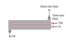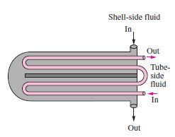 |
| 53 | ||||
| 374ad8 | João Lopes | 2025-03-13 11:57:41 | 54 | |
| 55 | > **Operation** **principle** |
|||
| 56 | > |
|||
| 57 | > In order to calculate the temperature difference ∆𝑡 in a 1-2 |
|||
| 58 | > exchanger, it is necessary to make some assumptions: |
|||
| 59 | > |
|||
| 60 | > 1\. The shell fluid temperature is an average isothermal temperature |
|||
| 61 | > at any cross section |
|||
| 62 | > |
|||
| 63 | > 2\. There is an equal amount of heating surface in each pass 3. The |
|||
| 64 | > overall coefficient of heat transfer is constant |
|||
| 65 | > |
|||
| 66 | > 4\. The specific heat of each fluid is constant 5. The flowrate of |
|||
| 67 | > each fluid is constant |
|||
| 68 | > |
|||
| 69 | > 6\. There are not phase change (evaporation or condensation) in a part |
|||
| 70 | > of the exchanger |
|||
| 71 | > |
|||
| 72 | > 7\. Heat losses are negligible |
|||
| 73 | > |
|||
| 74 | > The overall heat balance where ∆𝑡 is the true difference of |
|||
| 75 | > temperatures, is: |
|||
| 76 | > |
|||
| 77 | > 𝑄 = 𝑈𝐴∆𝑡 = 𝑊𝐶(𝑇 − 𝑇 ) = 𝑤𝑐(𝑡2 − 𝑡1) where U is the heat transfer |
|||
| 78 | > coefficient and A is the surface of contact. |
|||
| 79 | > |
|||
| 80 | > Shell-and-tube heat exchangers are complicated devices and the |
|||
| 81 | > simplified approaches should be used with care. In fact, it is assumed |
|||
| 82 | > that the overall heat transfer coefficient U is constant throughout |
|||
| 83 | > the heat exchanger and that the convection heat transfer coefficients |
|||
| 84 | > can be predicted using the convection correlations. However, in some |
|||
| 85 | > practical application, the predicted value of U can exceed 30 percent. |
|||
| 86 | > Thus, it is natural to tend to overdesign the heat exchangers in order |
|||
| 87 | > to avoid unpleasant surprises. |
|||
| 88 | > |
|||
| 89 | > Heat transfer enhancement in heat exchangers is usually accompanied by |
|||
| 90 | > increased |
|||
| 91 | > |
|||
| 92 | > pressure drop, and this causes higher pumping power. Therefore, any |
|||
| 93 | > gain from the enhancement in heat transfer should be balanced against |
|||
| 94 | > the cost of the accompanying pressure drop. Also, some thought should |
|||
| 95 | > be given to which fluid should pass through the tube side and which |
|||
| 96 | > through the shell side. Usually, the more viscous fluid is more |
|||
| 97 | > suitable for the shell side (larger passage area and lower pressure |
|||
| 98 | > drop) and the fluid with the higher pressure for the tube side. |
|||
| 99 | > |
|||
| 100 | > Usually, it is convenient to relate the equivalent temperature |
|||
| 101 | > difference to the log |
|||
| 102 | > |
|||
| 103 | > mean temperature difference relation for the counter-flow case as |
|||
| 104 | > |
|||
| 105 | > ∆ 𝑙𝑚 = 𝐹∆ 𝑙𝑚,𝐶𝐹 |
|||
| 106 | ||||
| 107 | where *F* is the correction factor**,** which depends on the geometry of |
|||
| 108 | the heat exchanger and the inlet and outlet temperatures of the hot and |
|||
| 109 | cold fluid streams. The |
|||
| 110 | ||||
| 111 | > ∆𝑇𝑚,𝐶𝐹 is the log mean temperature difference for the case of a |
|||
| 112 | > counter-flow heat exchanger with the same inlet and outlet |
|||
| 113 | > temperatures. |
|||
| 114 | > |
|||
| 115 | > The correction factor *F* for a shell-and-tube heat exchanger is shown |
|||
| 116 | > in the figures below versus two temperature ratios *P* and *R* defined |
|||
| 117 | > as |
|||
| 118 | > |
|||
| 119 | > 𝑡2 − 𝑡1 𝑇 − 𝑡1 |
|||
| 120 | > |
|||
| 121 | > 𝑇 − 𝑇 𝑡2 − 𝑡1 |
|||
| 122 | > |
|||
| 123 | > where the subscripts 1 and 2 represent the inlet and outlet*,* |
|||
| 124 | > respectively. Note that for |
|||
| 125 | > |
|||
| 126 | > a shell-and-tube heat exchanger, *T* and *t* represent the shell-side |
|||
| 127 | > and tube-side temperatures, respectively. |
|||
| 128 | ||||
| 62c67d | João Lopes | 2025-03-13 12:01:58 | 129 | 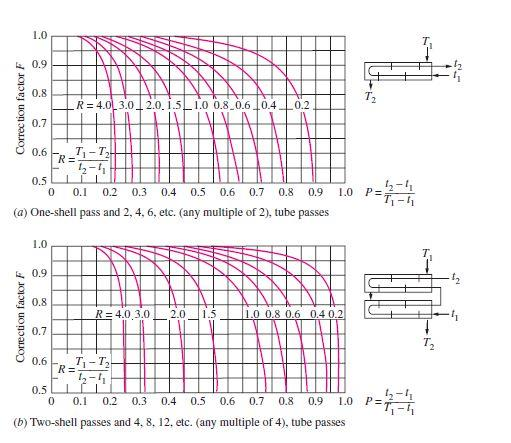 |
| 374ad8 | João Lopes | 2025-03-13 11:57:41 | 130 | |
| 131 | > **Factors** **that** **influence** **performances** *Fouling:* |
|||
| 132 | > |
|||
| 133 | > The performance of heat exchangers usually deteriorates with time as a |
|||
| 134 | > result of accumulation of deposits on heat transfer surfaces. The |
|||
| 135 | > layer of deposits represents additional resistance to heat transfer |
|||
| 136 | > and this causes a decrease of the rate of heat transfer in a heat |
|||
| 137 | > exchanger. The net effect of these accumulations on heat transfer is |
|||
| 138 | > represented by a fouling factor, which is a measure of the thermal |
|||
| 139 | > resistance introduced by fouling. |
|||
| 140 | > |
|||
| 141 | > For a shell-and-tube heat exchanger it possible to write the overall |
|||
| 142 | > heat transfer relation as |
|||
| 143 | > |
|||
| 144 | > 𝑈𝐴𝑠 = 𝑈𝐴𝑖 = 𝑈0𝐴0 = 𝑅 = ℎ𝑖𝐴𝑖 + 𝐴𝑖𝑖 + ln𝑈0𝐴0 𝑖) + 𝐴0 + ℎ0𝐴0 |
|||
| 145 | > |
|||
| 146 | > where 𝐴𝑖 = 𝐷𝐿 and 𝐴0 = 𝐷0𝐿 L are the areas of inner and outer |
|||
| 147 | > surfaces, and 𝑅,𝑖 and 𝑅,0 are the fouling factors at those surfaces. |
|||
| 148 | > |
|||
| 149 | > *Heat* *transfer* *rate:* |
|||
| 150 | > |
|||
| 151 | > The heat transfer rate is the most important parameter of a heat |
|||
| 152 | > exchanger. A heat exchanger should be capable of transferring heat at |
|||
| 153 | > the specified rate in order to achieve the desired temperature change |
|||
| 154 | > of the fluid at the specified mass flow rate. |
|||
| 155 | > |
|||
| 156 | > *Size* *and* *Weight:* |
|||
| 157 | > |
|||
| 158 | > The heat exchanger is better if it is smaller and lighter, in |
|||
| 159 | > particular, in the automotive and aerospace industries, where size and |
|||
| 160 | > weight requirements are most stringent. For this reason, |
|||
| 161 | > shell-and-tube heat exchangers cannot be used in this type of |
|||
| 162 | > application. Also, a larger heat exchanger normally carries a higher |
|||
| 163 | > price tag. The space available for the heat exchanger in some cases |
|||
| 164 | > limits the length of the tubes that can be used. |
|||
| 165 | > |
|||
| 166 | > *Material:* |
|||
| 167 | > |
|||
| 168 | > The thermal and structural stress effects need not be considered at |
|||
| 169 | > pressures below 15 *atm* or temperatures below 150*°C*. But these |
|||
| 170 | > effects are major considerations above 70 *atm* or 550*°C* and |
|||
| 171 | > seriously limit the acceptable materials of the heat exchanger. |
|||
| 172 | > |
|||
| 173 | > A temperature difference of 50*°C* or more between the tubes and the |
|||
| 174 | > shell will probably pose differential thermal expansion problems and |
|||
| 175 | > needs to be considered. In the case of corrosive fluids, we may have |
|||
| 176 | > to select expensive corrosion-resistant materials such as stainless |
|||
| 177 | > steel or even titanium. |
|||
| 178 | > |
|||
| 179 | > **Cost** |
|||
| 180 | > |
|||
| 181 | > The purchase cost of a shell and tube depends on the rear head type |
|||
| 182 | > and on the heat transfer |
|||
| 183 | > |
|||
| 184 | > area (size factor). The relationship between the purchase cost and the |
|||
| 185 | > size factor is |
|||
| 186 | > |
|||
| 187 | > represented in the graph below |
|||
| 188 | ||||
| 62c67d | João Lopes | 2025-03-13 12:01:58 | 189 | 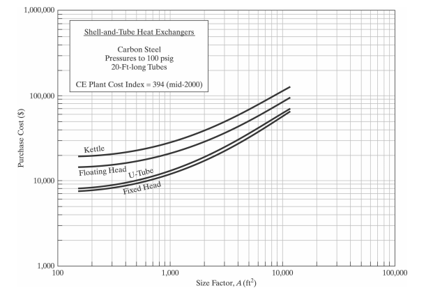 |
| 374ad8 | João Lopes | 2025-03-13 11:57:41 | 190 | |
| 191 | > Both fluids are usually forced to flow by pumps or fans that consume |
|||
| 192 | > electrical power. The annual cost of electricity associated with the |
|||
| 193 | > operation of the pumps and fans can be determined from |
|||
| 194 | > |
|||
| 195 | > 𝑂𝑝𝑒𝑟𝑎𝑡𝑖𝑛𝑔𝐶𝑜𝑠𝑡 = 𝑃𝑢𝑚𝑝𝑖𝑛𝑔𝑃𝑜𝑤𝑒𝑟\[𝑘𝑊\] × 𝐻𝑜𝑢𝑟𝑠𝑜𝑓𝑂𝑝𝑒𝑟𝑎𝑡𝑖𝑜𝑛\[ℎ\] × |
|||
| 196 | > 𝑃𝑟𝑖𝑐𝑒𝑜𝑓𝐸𝑙𝑒𝑐𝑟𝑖𝑐𝑖𝑡𝑦\[\$ 𝑘𝑊ℎ\] |
|||
| 197 | > |
|||
| 198 | > where the pumping power is the total electrical power consumed by the |
|||
| 199 | > motors of the pumps and fans. |
|||
| 200 | > |
|||
| 201 | > Minimizing the pressure drop and the mass flow rate of the fluids will |
|||
| 202 | > minimize the operating cost of the heat exchanger, but it will |
|||
| 203 | > maximize the size of the heat exchanger and thus the initial cost. As |
|||
| 204 | > a rule of thumb, doubling the mass flow rate will reduce the initial |
|||
| 205 | > cost by half but will increase the pumping power requirements by a |
|||
| 206 | > factor of roughly eight. Typically, fluid velocities encountered in |
|||
| 207 | > heat exchangers range between 0.7 and 7 m/s for liquids and between 3 |
|||
| 208 | > and 30 m/s for gases. Low velocities are helpful in avoiding erosion, |
|||
| 209 | > tube vibrations, and noise as well as pressure drop. |
|||
| 210 | > |
|||
| 211 | > **Advantages**: |
|||
| 212 | > |
|||
| 213 | > *Size:* |
|||
| 214 | > |
|||
| 215 | > Shell-and-tube heat exchangers are capable of providing a larger |
|||
| 216 | > surface area for heat transfer to take place while having a shorter |
|||
| 217 | > length overall due to presence of multiple tubes. |
|||
| 218 | > |
|||
| 219 | > *Heat* *duty:* |
|||
| 220 | > |
|||
| 221 | > Shell-and-tube heat exchangers can handle higher temperatures and |
|||
| 222 | > pressures and hence higher heat duty. This is because besides |
|||
| 223 | > providing a higher overall heat transfer coefficient, additions can |
|||
| 224 | > also be made to negate thermal expansion effects and the thickness can |
|||
| 225 | > also be varied (more in the next point). |
|||
| 226 | > |
|||
| 227 | > *Versatility:* |
|||
| 228 | > |
|||
| 229 | > From the design point of view, shell-and-tube heat exchangers are the |
|||
| 230 | > most versatile of all heat exchangers. Being tubular in shape, heads / |
|||
| 231 | > closures of required shape and thickness can be used. The number of |
|||
| 232 | > tubes and tube pitch can be selected according to operating |
|||
| 233 | > conditions. Expansion bellows can be used to negate thermal expansion |
|||
| 234 | > effects, baffles if different cuts and spacings can be used to |
|||
| 235 | > influence the overall heat transfer coefficients and there's even |
|||
| 236 | > something called a floating head which can be added to negate thermal |
|||
| 237 | > expansion of the tubes. The number of passes on shell side and tube |
|||
| 238 | > side can be altered as well. |
|||
| 239 | > |
|||
| 240 | > **Disadvantages**: |
|||
| 241 | > |
|||
| 242 | > *Size:* |
|||
| 243 | > |
|||
| 244 | > This can also be a disadvantage as at lower heat duty, there are more |
|||
| 245 | > compact heat exchangers such as plate type exchanger. Also, the |
|||
| 246 | > absence of hairpin bends causes shell-and-tube heat exchangers to take |
|||
| 247 | > up more space than double pipe heat exchangers in some cases. |
|||
| 248 | > |
|||
| 249 | > *Maintenance:* |
|||
| 250 | > |
|||
| 251 | > Cleaning of tubes is difficult and fouling is always an issue when |
|||
| 252 | > overall heat transfer coefficient is addressed. This requires periodic |
|||
| 253 | > cleaning of the shell as well as the tubes. Cleaning tubes may be more |
|||
| 254 | > difficult if the pitch is triangular. |
|||
| 255 | > |
|||
| 256 | > **Utilities** |
|||
| 257 | > |
|||
| 258 | > The selection of utilities to be used in the shell and tubes tube |
|||
| 259 | > exchanger takes into |
|||
| 260 | > |
|||
| 261 | > account the type of industry in which it is being operated and the |
|||
| 262 | > desired parameters, such as the required power, thermal stability and |
|||
| 263 | > thermal capacity. |
|||
| 264 | > |
|||
| 265 | > *Cooling* *Water*: |
|||
| 266 | > |
|||
| 267 | > Cooling water is used to cool and/or condense currents. The cooling |
|||
| 268 | > water circulates inside heat exchangers. About 80% of the temperature |
|||
| 269 | > reduction is due to the evaporation of the cooling water and the |
|||
| 270 | > transfer of heat to the surrounding air. |
|||
| 271 | > |
|||
| 272 | > *Steam:* |
|||
| 273 | > |
|||
| 274 | > Steam is the most common heat utility used in the chemical industry |
|||
| 275 | > and can be used to power pumps, compressors and heat exchangers. Using |
|||
| 276 | > steam allows a more efficient heat source since the heat of |
|||
| 277 | > condensation of the steam is quite high, which translates into a high |
|||
| 278 | > yield per utility mass, at a constant temperature. Another reason is |
|||
| 279 | > that steam is non-flammable, non-toxic and inert to various process |
|||
| 280 | > fluids (more safe than other utilities like oil). |
|||
| 281 | > |
|||
| 282 | > **Conclusion** |
|||
| 283 | > |
|||
| 62c67d | João Lopes | 2025-03-13 12:01:58 | 284 | > The simple design of a shell and tube heat exchanger makes it an ideal |
| 374ad8 | João Lopes | 2025-03-13 11:57:41 | 285 | > cooling solution for a wide variety of applications and as a |
| 286 | > consequence shell-and-tube heat exchangers are very popular and |
|||
| 287 | > commonly found in industrial use. |
|||
| 288 | > |
|||
| 289 | > **References** |
|||
| 290 | > |
|||
| 291 | > \[1\] Notes on Transfer Phenomena II, Professor Maria Graça Carvalho, |
|||
| 292 | > 2018/2019; |
|||
| 293 | > |
|||
| 294 | > \[2\] Warren D. Seider, University of Pennsylvania |
|||
| 295 | > |
|||
| 296 | > \[3\] Heat Transfer by Changel 2nd Edition |
|||
| 297 | > |
|||
| 298 | > \[4\] Heat Transfer by Holman 6th Edition |