

Departamento de Engenharia Química
Mestrado Integrado em Engenharia Química
Integração e intensificação de processos
Shell and Tubes Heat Exchangers
Docente Responsável:
Nuno Manuel Clemente de Oliveira
Integrantes do grupo:
João Victor Vieira
Matteo Gecchele
Introduction & Structure
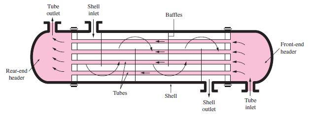
The most common type of heat exchanger is the shell-and-tube, usually used in a lot of industrial applications. This type of heat exchanger has large number of tubes, sometimes several hundred, packed in a shell with their axes parallel to that of the shell. The heat transfer takes place between two fluid, one flowing inside the tubes and one flowing outside the tubes through the shell. Baffles are commonly placed in the shell to force the shell-side fluid to flow across the shell to enhance heat transfer, to maintain uniform spacing between the tubes and, also in order to maintain the turbulent flow inside the exchanger. The baffle spacing is usually not greater than a distance equal to the inside diameter or closer than a distance equal to one-fifth the inside diameter of the shell.
Usually the shell-and-tube heat exchangers have large size and weight, and for this reason they are not using in automotive and aircraft applications. At both ends of the shell, the tubes open to some large flow areas, called headers, where the tube-side fluid accumulates before entering the tubes and after leaving them.
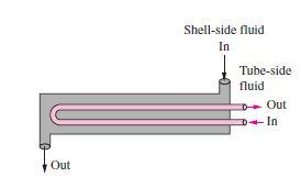
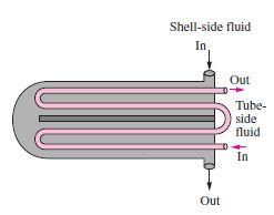
Shell-and-tube heat exchangers are further classified according to the number of shell and tube passes involved. Heat exchangers in which all the tubes make one U-turn in the shell, for example, are called one-shell-pass and two-tube-passes heat exchangers. Likewise, a heat exchanger that involves two passes in the shell and four passes in the tubes is called a two-shell- passes and four-tube-passes heat exchanger.
Operation principle
In order to calculate the temperature difference ∆𝑡 in a 1-2 exchanger, it is necessary to make some assumptions:
1. The shell fluid temperature is an average isothermal temperature at any cross section
2. There is an equal amount of heating surface in each pass 3. The overall coefficient of heat transfer is constant
4. The specific heat of each fluid is constant 5. The flowrate of each fluid is constant
6. There are not phase change (evaporation or condensation) in a part of the exchanger
7. Heat losses are negligible
The overall heat balance where ∆𝑡 is the true difference of temperatures, is:
𝑄 = 𝑈𝐴∆𝑡 = 𝑊𝐶(𝑇 − 𝑇 ) = 𝑤𝑐(𝑡2 − 𝑡1) where U is the heat transfer coefficient and A is the surface of contact.
Shell-and-tube heat exchangers are complicated devices and the simplified approaches should be used with care. In fact, it is assumed that the overall heat transfer coefficient U is constant throughout the heat exchanger and that the convection heat transfer coefficients can be predicted using the convection correlations. However, in some practical application, the predicted value of U can exceed 30 percent. Thus, it is natural to tend to overdesign the heat exchangers in order to avoid unpleasant surprises.
Heat transfer enhancement in heat exchangers is usually accompanied by increased
pressure drop, and this causes higher pumping power. Therefore, any gain from the enhancement in heat transfer should be balanced against the cost of the accompanying pressure drop. Also, some thought should be given to which fluid should pass through the tube side and which through the shell side. Usually, the more viscous fluid is more suitable for the shell side (larger passage area and lower pressure drop) and the fluid with the higher pressure for the tube side.
Usually, it is convenient to relate the equivalent temperature difference to the log
mean temperature difference relation for the counter-flow case as
∆ 𝑙𝑚 = 𝐹∆ 𝑙𝑚,𝐶𝐹
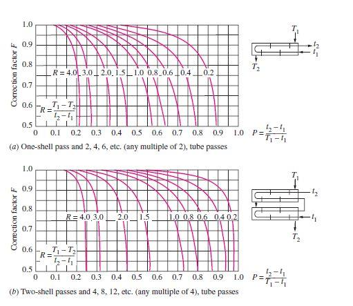
where F is the correction factor, which depends on the geometry of the heat exchanger and the inlet and outlet temperatures of the hot and cold fluid streams. The
∆𝑇𝑚,𝐶𝐹 is the log mean temperature difference for the case of a counter-flow heat exchanger with the same inlet and outlet temperatures.
The correction factor F for a shell-and-tube heat exchanger is shown in the figures below versus two temperature ratios P and R defined as
𝑡2 − 𝑡1 𝑇 − 𝑡1
𝑇 − 𝑇 𝑡2 − 𝑡1
where the subscripts 1 and 2 represent the inlet and outlet, respectively. Note that for
a shell-and-tube heat exchanger, T and t represent the shell-side and tube-side temperatures, respectively.
Factors that influence performances Fouling:
The performance of heat exchangers usually deteriorates with time as a result of accumulation of deposits on heat transfer surfaces. The layer of deposits represents additional resistance to heat transfer and this causes a decrease of the rate of heat transfer in a heat exchanger. The net effect of these accumulations on heat transfer is represented by a fouling factor, which is a measure of the thermal resistance introduced by fouling.
For a shell-and-tube heat exchanger it possible to write the overall heat transfer relation as
𝑈𝐴𝑠 = 𝑈𝐴𝑖 = 𝑈0𝐴0 = 𝑅 = ℎ𝑖𝐴𝑖 + 𝐴𝑖𝑖 + ln𝑈0𝐴0 𝑖) + 𝐴0 + ℎ0𝐴0
where 𝐴𝑖 = 𝐷𝐿 and 𝐴0 = 𝐷0𝐿 L are the areas of inner and outer surfaces, and 𝑅,𝑖 and 𝑅,0 are the fouling factors at those surfaces.
Heat transfer rate:
The heat transfer rate is the most important parameter of a heat exchanger. A heat exchanger should be capable of transferring heat at the specified rate in order to achieve the desired temperature change of the fluid at the specified mass flow rate.
Size and Weight:
The heat exchanger is better if it is smaller and lighter, in particular, in the automotive and aerospace industries, where size and weight requirements are most stringent. For this reason, shell-and-tube heat exchangers cannot be used in this type of application. Also, a larger heat exchanger normally carries a higher price tag. The space available for the heat exchanger in some cases limits the length of the tubes that can be used.
Material:
The thermal and structural stress effects need not be considered at pressures below 15 atm or temperatures below 150°C. But these effects are major considerations above 70 atm or 550°C and seriously limit the acceptable materials of the heat exchanger.
A temperature difference of 50°C or more between the tubes and the shell will probably pose differential thermal expansion problems and needs to be considered. In the case of corrosive fluids, we may have to select expensive corrosion-resistant materials such as stainless steel or even titanium.
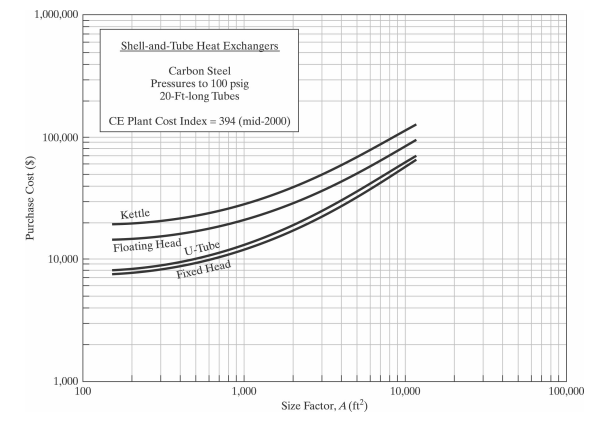
Cost
The purchase cost of a shell and tube depends on the rear head type and on the heat transfer
area (size factor). The relationship between the purchase cost and the size factor is
represented in the graph below
Both fluids are usually forced to flow by pumps or fans that consume electrical power. The annual cost of electricity associated with the operation of the pumps and fans can be determined from
𝑂𝑝𝑒𝑟𝑎𝑡𝑖𝑛𝑔𝐶𝑜𝑠𝑡 = 𝑃𝑢𝑚𝑝𝑖𝑛𝑔𝑃𝑜𝑤𝑒𝑟[𝑘𝑊] × 𝐻𝑜𝑢𝑟𝑠𝑜𝑓𝑂𝑝𝑒𝑟𝑎𝑡𝑖𝑜𝑛[ℎ] × 𝑃𝑟𝑖𝑐𝑒𝑜𝑓𝐸𝑙𝑒𝑐𝑟𝑖𝑐𝑖𝑡𝑦[$ 𝑘𝑊ℎ]
where the pumping power is the total electrical power consumed by the motors of the pumps and fans.
Minimizing the pressure drop and the mass flow rate of the fluids will minimize the operating cost of the heat exchanger, but it will maximize the size of the heat exchanger and thus the initial cost. As a rule of thumb, doubling the mass flow rate will reduce the initial cost by half but will increase the pumping power requirements by a factor of roughly eight. Typically, fluid velocities encountered in heat exchangers range between 0.7 and 7 m/s for liquids and between 3 and 30 m/s for gases. Low velocities are helpful in avoiding erosion, tube vibrations, and noise as well as pressure drop.
Advantages:
Size:
Shell-and-tube heat exchangers are capable of providing a larger surface area for heat transfer to take place while having a shorter length overall due to presence of multiple tubes.
Heat duty:
Shell-and-tube heat exchangers can handle higher temperatures and pressures and hence higher heat duty. This is because besides providing a higher overall heat transfer coefficient, additions can also be made to negate thermal expansion effects and the thickness can also be varied (more in the next point).
Versatility:
From the design point of view, shell-and-tube heat exchangers are the most versatile of all heat exchangers. Being tubular in shape, heads / closures of required shape and thickness can be used. The number of tubes and tube pitch can be selected according to operating conditions. Expansion bellows can be used to negate thermal expansion effects, baffles if different cuts and spacings can be used to influence the overall heat transfer coefficients and there's even something called a floating head which can be added to negate thermal expansion of the tubes. The number of passes on shell side and tube side can be altered as well.
Disadvantages:
Size:
This can also be a disadvantage as at lower heat duty, there are more compact heat exchangers such as plate type exchanger. Also, the absence of hairpin bends causes shell-and-tube heat exchangers to take up more space than double pipe heat exchangers in some cases.
Maintenance:
Cleaning of tubes is difficult and fouling is always an issue when overall heat transfer coefficient is addressed. This requires periodic cleaning of the shell as well as the tubes. Cleaning tubes may be more difficult if the pitch is triangular.
Utilities
The selection of utilities to be used in the shell and tubes tube exchanger takes into
account the type of industry in which it is being operated and the desired parameters, such as the required power, thermal stability and thermal capacity.
Cooling Water:
Cooling water is used to cool and/or condense currents. The cooling water circulates inside heat exchangers. About 80% of the temperature reduction is due to the evaporation of the cooling water and the transfer of heat to the surrounding air.
Steam:
Steam is the most common heat utility used in the chemical industry and can be used to power pumps, compressors and heat exchangers. Using steam allows a more efficient heat source since the heat of condensation of the steam is quite high, which translates into a high yield per utility mass, at a constant temperature. Another reason is that steam is non-flammable, non-toxic and inert to various process fluids (more safe than other utilities like oil).
Conclusion
The simple design of a shell and tube heat exchanger makes it an ideal cooling solution for a wide variety of applications and as a consequence shell-and-tube heat exchangers are very popular and commonly found in industrial use.
References
[1] Notes on Transfer Phenomena II, Professor Maria Graça Carvalho, 2018/2019;
[2] Warren D. Seider, University of Pennsylvania
[3] Heat Transfer by Changel 2nd Edition
[4] Heat Transfer by Holman 6th Edition